

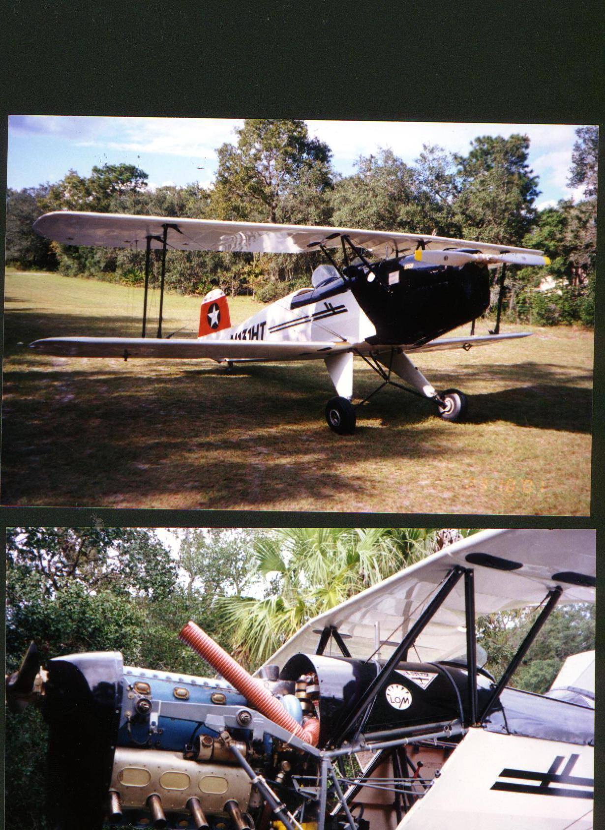
 LOM 332Sc installed on Jungmann N28BU
LOM Piston engines were manufactured in Prague in the Czech Republic from about 1960 onwards. Over the years production has started and stopped numerous times but spare parts supply and overhaul capabilities continue today. There are always rumors that production is about to restart, but it who knows?
http://www.pistovemotory.cz/en/
LOM is a large enterprise. They manufacture or overhaul piston engines, jet engines, helicopters and fixed wing aircraft, particularly MIG, Mil and Let aircraft. For this reason, LOM can be a challenge to communicate with. Imagine trying to buy an AN hex bolt from Northrop-Grumman and you will get an idea of what you sometimes have to go through. On the other hand, there are many small independent aviation maintenance organizations throughout the former Eastern Europe that have expertise in these engines.
Developed from the earlier Walter piston engines, the LOM come in four basic models: Six cylinder, four cylinder, with supercharger and without. The first digit in the model number digit is the super charger configuration. 3 = supercharged, 1 = normally aspirated. The last digit indicates the number of cylinders: 7 = six cylinders, 2 = four. Hence a model M332 is a 4 cylinder supercharged model. an M137 is a six cylinder normally aspirated model. The logic behind this is not obvious,
The model numbers also have suffixes, most commonly Sc, A, C and AK. The earliest engines are marked Sc, Other letters indicate aerobatic capability (continuous or intermittent) etc. This table provides a guide to the naming conventions: http://www.pistovemotory.cz/en/engines
Aerobatic capabilities are provided by two built-in gravity valves that control the scavenging of oil from the engine back to the tank. Amusingly the extended TBO feature is just a piece of paper. A change to the operators manual states that if run on exclusively Aeroshell ashless dispersant oil or equivalent, the TBO is automatically extended from 1400 to 2000 hours.
Philosophy and reliability
I spend quite a bit of time on the phone and via email trying to help people with LOM piston engines. They generally fall into two categories: They operate the engine exactly as prescribed by the LOM manuals and enjoy such perfect reliability that they seldom even bother opening the cowling OR - they assume that LOM don't really know what they are doing and operate the engine like the local A&P/Lycoming expert thinks. If I had a dollar for every time I have heard "Well my buddy builds race car engines and he says . . . ". The moral is clear. Operate it by the LOM book and you will enjoy thousands of hours of reliable flying. Run it like a Lycoming with the mixture full rich, no valve adjustment and Lycoming torque values and you are in for a world of pain.
There is a difference in Philosophy between (former) East block engineering and American/European engineering and that is repeatability. If you buy a part from Lycoming, a piston pin say, it will arrived polished and ready to install. You can expect a perfect fit every time. LOM engines on the other hand are hand built. During assembly each part is measured, adjusted and custom fit to ensure a perfect result. As an example of this philosophy, you do not simply order a cam cover gasket. You must fit/torque the cam cover, measure the gap between the cover and the cylinder head and then order a gasket of the correct thickness. They come in ten different thicknesses. Here again you can see where slapping on a replacement part and tightening the nuts is just not going to work on these engines. People sometimes report oil leaks from the engine. Now you can probably guess why!
Design
LOM piston engines are of a significantly more modern design that the typical Continental or Lycoming engine. Amongst other features they have:
- Automatic advance and retard ignition systems to promote easy starting and high power output
- Multipoint sequential fuel injection as found on new cars
- Automatic altitude compensation
- Automatic stating enrichment
- Overhead cam
- Baffling installed from the factory resulting in a ready to install engine
- Built-in unlimited inverted flight operation with no external valves or plumbing
- Optional supercharger for aerobatics, shorter takeoff and high altitude operation
- Quiet, low current starter motor
- Slim profile ideal for tandem seat aircraft.
- Light weight
- Very smooth operation
- These are low cubic capacity, high RPM engines. The M332 for example can theoretically produce 160 HP but it does so at 3,000 RPM. This requires a pretty small propeller.
- The clutched supercharger means that you can choose different power configurations (and fuel consumptions) in flight, but then you really need two propellers. The prop becomes even more of a compromise than usual.
- Maintenance of the engines requires strict adherence to the manual. There is no "Bolt it on and go"
- At every fly-in you attend someone will ask "What type of Ranger is that?" and then go on to expound on how "you will never get spares for that". (At the time of writing, LOM spares are easier to get than Lycoming. email the factory, wire them some money and in a few days they turn up by UPS.)
- Because this is an overhead cam engine, removing a cylinder is not an easy task at all. The entire camshaft housing, the fuel injection pump and all the baffling must be removed before even one cylinder to be pulled. This is a major operation!
Overall, pros and cons considered, I would not want to give up the LOM engine in N28BU. It is smooth, reliable, looks good and provides a nice experience for front seat passengers. I cannot climb as fast as a Lycoming Jungmann but then again I can climb at least twice as fast as a Rangsdorf or Altenrhine original.
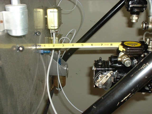
The Fuel System
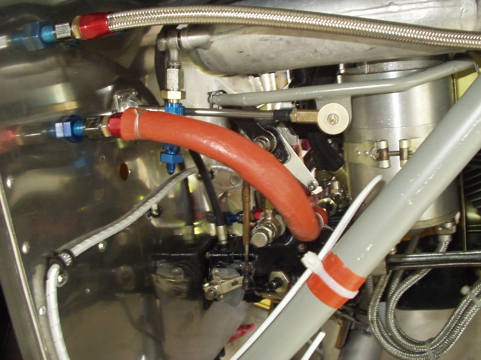
The heart of the LOM fuel system is the LOM 5051 fuel injection pump.

The pump has three main sections: A low pressure vane pump with regulator, a pressure sensing capsule, and a high pressure pump.
Looking at the picture above you will see that fuel from the tank enters a fitting attached to a black cylinder running across the top of the pump. This is the low pressure fuel pump. Its job it to create a steady pressure of around 4 or 5 PSI and to deliver that fuel via the steel pipe closest to the camera into the high pressure section. The low pressure pump has a built in filter and pressure regulator which are under the acorn nut that secures the inlet fitting.
To the far right of the pump pictured above are the pressure sensing aneroids. The aneroids expand and contract depending on the manifold pressure, sensed via the small fitting on the top of the chamber.

Pressure sensing aneroid capsules
The aneroids press against this plunger which instructs the high pressure pump exactly how much fuel to inject into the engine.

There are three further mechanisms by which the air/fuel mixture is controlled: The aneroids are also sensitive to atmospheric pressure (they measure the difference between manifold and ambient pressure) so as altitude changes, the mixture is automatically adjusted. There is also a manual override. On the right side of the pump a mixture lever is provided with a graduated scale marked '+', '-' and 'N'. 'N' is the normal position. The system is typically left in that position allowing the pump to automatically regulate fuel flow. In most cases the manual override is never used and in fact it is often permanently wired in the 'N' position.

Finally, on examining the mounting flange where the pump is mounted to the engine, a small oil pressure sensing hole will be observed. The pump uses this to automatically enrich the mixture when the oil pressure is very low as when starting the engine. This acts like a manual choke providing the engine with extra fuel to help starting.

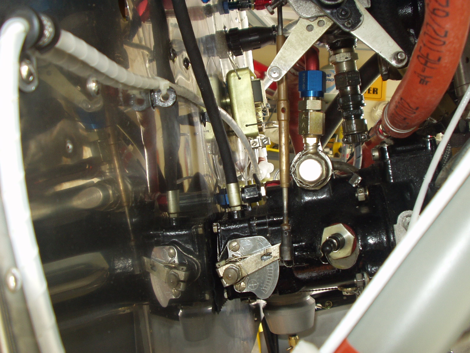
And that brings us to the high pressure section. Imagine four (or six) medical type syringes stacked side-by-side. The outlet of each syringe is connected to a fuel injector nozzle in one of the four (or six) cylinders. Pressing against the plungers of the syringes there is a gear wheel on the surface of which is a cam. As the wheel rotates the plunger of each syringe is depressed one after the other by the cam in the correct engine firing order. Fuel is injected at +/- 100 PSI.
Now to complete the picture, that gear wheel with the cam that operates the syringes is mounted on a sliding shaft and is pushed closer to, or further from the syringe plungers by the aneroid capsule plunger. The higher the manifold pressure/atmospheric pressure, the closer the gear comes to the syringes and the more fuel is delivered to the engine.
Clever stuff!
This YouTube video shows a cut-away pump from and LOM332 in action
and here the operation of a disassembled pump is shown.
The ignition system
Ignition is provided by two magnetos in the traditional manner. The magnetos are manufactured by the PAL company but under license from Scintilla and are closely related to the American company Vertex which still makes magnetos popular in auto racing and in VW aircraft conversions. Many Vertex components, certainly points, condensers (capacitors) etc are interchangeable.

Engine static timing can be set by loosening the band clamp and rotating the magneto body as desired.
The magnetos used on LOM engines have automatic advance/retard. The initial, static timing is set to 7° before top dead center. At about 1,400 RPM, the advance mechanism operates and the timing changes to +/- 24°. In practice, the timing is not set in this way, however. The manual simply states that the ignition should be adjusted until an exactly 25 RPM mag drop is observed at maximum RPM on the ground. More than 25 RPM means the timing is too far retarded. Less and it is too far advanced. The timing should be checked at least once a year. The RPM drop seems to diminish over time and need readjustment.
The mags do not have impulse couplings. To aid in starting they are supplied with a mechanical vibrator (shower of sparks). This works well enough but it does require cleaning and adjustment from time to time. A very common modification is the substitution of a "SlickStart" device. Being solid state these require no adjustment and with an operating voltage from 9v to 32v a good start is assured with even the weakest of batteries.

Slickstart solid state ignition booster
Another very common update is substituting NGK spark plugs for the original expensive and hard to find Czech plugs. This requires new wires, plugs and caps as follows:
Spark plugs: NGK DR8HS
Plug caps: NGK LB05FP
Wire: Solid Core 8mm MOROSO Blue MAX
These components are inexpensive and are designed for magneto operation. Here are a few pictures of the conversion process:


Electrical system
LOM engines are supplied with a 24v generator and regulator. (A few examples were produced with 12v electrical systems for the US market, but these are best avoided) Unfortunately the generator weighs about the same as a mid-sized family car. There is a nice alternative though. B&C specialty company sell a very light weight dynamo for the LOM engine. https://bandc.com/product/alternator-for-lom-10-amps-homebuilt/#regulator Order the 12v or 24v version as appropriate. DO NOT order the 30 amp version. I have seen several of these installed in the field and in every single case the crank case assembly had cracked due to the unsupported weight of the larger alternator.
The starter fitted to the engine is small and light weight requiring only a very small battery. (A 10AH sealed lead-acid battery is plenty) The reason that the starter is so small is that it drives the engine through the supercharger gearbox and hence benefits from a 16:1 reduction ratio. This means that to start the engine, the supercharger MUST be engaged. If it is not, the starter will spin but the engine will not turn. The starter engagement solenoid is built into the supercharger housing. In an emergency the starter solenoid can be operated manually. Remove the silver cap from the rear of the starter assembly to expose the end of the solenoid, then press the solenoid armature in towards the engine.

Baffling
Like many in-line engines, the baffling is factory installed, very effective and requires no work at installation. Bolt the engine to the mount and you are done. - No rubber baffling material, no high temp silicone. Everything is already in place and ready to go.
Supercharger
LOM models ending in a '2' have a centrifugal supercharger which is connected to the crankshaft via a 16:1 epicyclic gear drive and clutch (band brake). The band brake is operated with a cockpit control; either a cable, pushrod or electric linear actuator. When the supercharger is engaged, +/- 20 more HP are available (on the M332AK) I typically use the supercharger for starting, takeoff/climb and for aerobatics. For cross-country flight and hopping passengers I generally switch it off. But why? What is the difference between 100% throttle with the supercharger off and 90% throttle with it on? - I don't know. The LOM operators manual says to turn it off when not needed and suggests that the a/c is always parked with it off to ensure the band brake does not stick to the main gear.

Because of the supercharger I like to have a manifold pressure gauge in the cockpit and this is actually my main instrument for setting power, particularly since the Performance Propeller "Almost constant speed" prop I use hardly changes RPM at all with power changes.
Plumbing
In general the LOM engine is quite easy to hook up. The only external connections required are:
- Oil in from the tank
- Oil return to the tank
- Oil pressure to the cockpit gauge
- Fuel pressure to the cockpit gauge
- Fuel from the tank
- Return furl to the tank
- Primer
Instrumentation
All "standard" instruments may be used but there are two interesting considerations. The engine is supplied with a tach generator on the right side of the engine connected to a 90 degree drive. The UMA company make a 3 1/8" recording tach designed for LOM engines and this provides a much lighter weight alternative. The original tach drive can be removed and the UMA adaptor connected to the alternative tach drive on the back of the oil pump.
Order the tach here and specify the LOM adaptor. https://umainstruments.com/aviation-instruments/non-tso-engine-instruments/electronic-tachometers/
I also recommend fitting a manifold pressure gauge, even with a fixed pitch prop. This will help you better measure the engine power and supercharger performance.
Electrical system
LOM engines are supplied with a generator and generator control unit. While these work well enough they are very large and heavy. It is common to replace the generator system with a more modern, light weight "alternator" from B & C Specialty. B & C make two systems for LOM engines, The BC413-H provides 30 amps, the BC414-H can supply 10 amps. Buy the BC414-H. Unfortunately the 30 amp device is heavier and longer producing more stress on the mounting. I have encounter five installations of the BC413H and in every single instance, the LOM generator drive housing had cracked and was laking oil. I have seen no issues with the 10 amp unit. It is a very common upgrade.
https://bandc.com/product-category/alternators/experimental-alternators/page/2/
Resources
LOM Praha website: http://www.pistovemotory.cz/en/
LOM manuals (Spare parts, installation, operator's manual etc) : http://www.pistovemotory.cz/en/support
Overhaul manual: Overhaul.pdf
Overhaul manual - Extra pages.pdf
AvioService Belgrade (Good source for used parts): https://www.avioservicebgltd.com/Spare%20parts%20for%20ZLIN.html
Installation
Many new LOM pictures have been provided by Benoit Dierickx and may be found in the image gallery here: LOM installation.
There were a number of challenges to be faced in making my own LOM installation. Challenges that would have been avoided had I used Joe Krybus' system but I guess I wanted to do it my way.
Here are some recent pictures of the way in which some of those challenges were met:
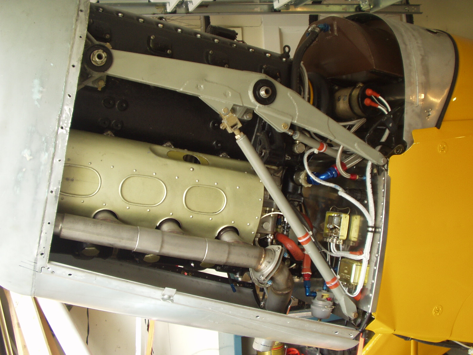
This picture shows the modified GlasStar exhaust system from Moravia, the starter motor rotated 90 degrees and my home made oil tank.
Here is my throttle linkage. With the engine so close to the firewall, there was no room for a mechanical linkage. Instead, I re-made the pushrod from steel tube instead of the original aluminum and welded a tab to it. My flexible throttle cable attaches to the tab through a rod-end bearing (which is hidden behind the large washer).
Conversation with other LOM operators have led me to believe that an in-flight mixture control is not really necessary. I turned the LOM push-rod into a turnbuckle so that my mixture is ground adjustable.
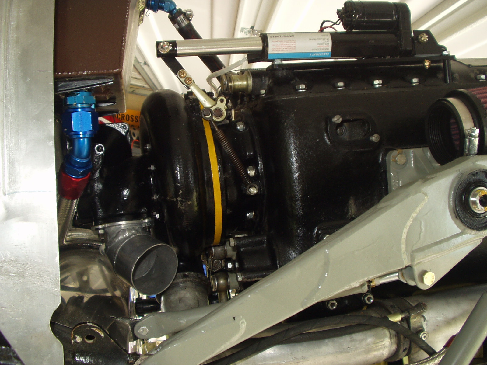
Here you can see my welded aluminum elbow for the air intake, the aluminum oil tank and my linear electric actuator that controls the super charger. It has a travel of 4" and a thrust of 70 pounds. It engages or disengages the super charger in about 2 seconds from a small switch mounted on the throttle quadrant.
The K&N air cleaner will mount to a bracket I am making that screws onto the opening near the top of the engine case.
I will document here the process I have endured in installing the LOM332 engine my way. I say "my way" because Joe Krybus will provide a complete kit to install the engine in a very straightforward way. As always, the quality of his products is fantastic. Those wishing to complete the engine change wile still young enough to fly the result would be well advised to use's Joe's kit.
The LOM is much lighter than the Tigre of course so being based on the Czech Aero 104 airframe, Joe mounts the engine quite far forward. This maintains good access to the accessory section of the engine. I felt that with careful attention to the weight of the rear of the aircraft, battery placement etc., it would be possible to put the engine further back so that an original Spanish cowl could be used. With 13 years of flying now under its wings, the aircraft seems to bear this out.
This is purely a matter of preference. Joe's installation is almost exactly the same dimensions as a Czech Aero C-104 so his installations look very much like that aircraft. The German/Swiss Hirth installation is a little shorter, the Spanish Tigre the shortest of all. I happen to like the look of the Spanish cowl the best.
I chose to shorten the mount by 6 inches
It turns out that I was not alone in. Talmadge Scott from Florida had exactly the same idea and has already flown his aircraft. To fit the engine exactly in original Spanish sheet metal, Talmadge relocated one of the tubes in the forward fuselage to allow the engine to protrude about an inch through the firewall. He then covered this protrusion with a stainless steel cover.
Talmadge Scott's LOM Jungmann
I took a slightly different approach. I found that the prop. hub from a Walter Minor engine fits the LOM perfectly but moves the prop aft about 1.5". This allows the prop. to be placed in the original place without the protrusion through the firewall. These prop hubs are now available for purchase from Moravia where it is listed as a "Bucker style" prop hub.

Walter Minor prop. hub
I had already bought my engine mount from Joe Krybus when I took the decision to remount the engine in this way. I made a wooden jig to help get the alignment just right and then cut and re-welded the mount to move the engine aft. You will find pictures of the process here and a sketch at the bottom of this page.

Original Krybus Mount Modified mount
Since I don't have an original cowl (my project came with no sheet metal) my next task is to build one. I have recruited a local race car body builder to help me get that nice curve in the top of the Spanish cowl.
Other factors to be considered in installing an LOM engine are:
Oil tank
The Spanish oil tank will no longer fit in it's original position on the firewall. I may use a Joe Krybus tank (which still fits the shorter mount) or I may make a saddle tank to fit in the space over the engine.
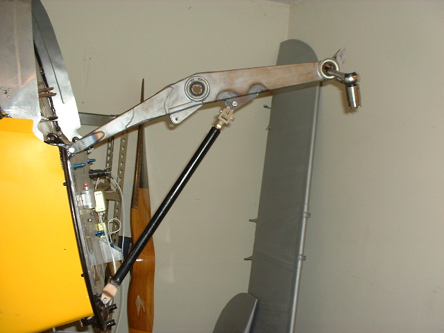
Supercharger control
The LOM supercharger control is a push-pull rod that required a force of about 50 lbs to operate. This is something of a challenge to arrange. Talmadge welded a tube through his fuel tank. Other have used a system of cranks and levers. I have taken a different approach. The Warner Electric company make a linear electric actuator which exerts a force of 70 lbs over a throw of 4 inches. It is about six inches long and very slim. I have mounted one of these units on top of the engine and control my supercharger from a toggle switch hidden behind the throttle quadrant. I used Warner model number S24-17A8-04. A more detailed description can be found here:
http://www.powerdrives.com/electrak/S24-17A8-04.htm
The decive costs a modest (by airplane standards) $175
Fuel System
Like many fuel injected engines, the LOM returns pressure bypass fuel to the tank. An extra port should be provided to allow this.
Finally, if I had to do it again, I would definitely not choose this approach. If you look at a Tigre tubular mount, you will see that it is very similar indeed to this mount, intended to attach an LOM to a GlasSstar. I would buy the mounting pads, rubber mounts and carriers and then weld-up a tubular mount similar to this. It would be much quicker and cheaper.
Steve

Notice the neat exhaust system available from Moravia.