
Many new LOM pictures have been provided by Benoit Dierickx and may be found in the image gallery here: LOM installation.
There were a number of challenges to be faced in making my own LOM installation. Challenges that would have been avoided had I used Joe Krybus' system but I guess I wanted to do it my way.
Here are some recent pictures of the way in which some of those challenges were met:
This picture shows the modified GlasStar exhaust system from Moravia, the starter motor rotated 90 degrees and my home made oil tank.
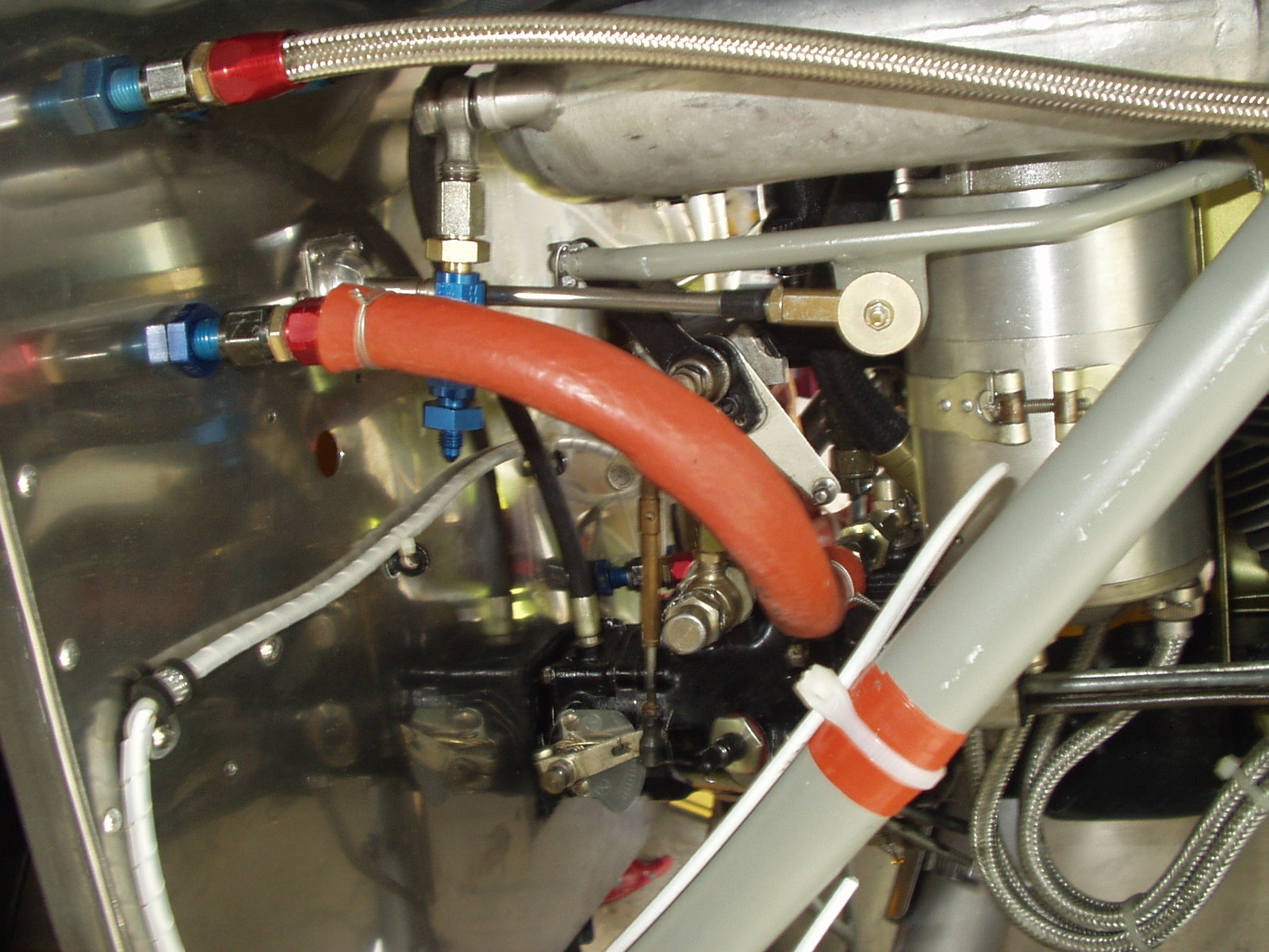
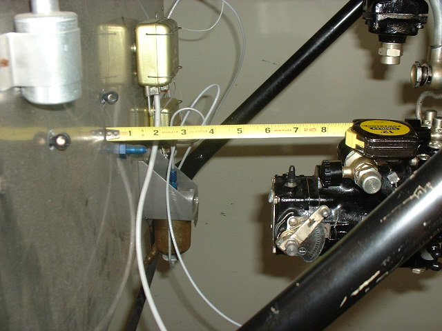
Here is my throttle linkage. With the engine so close to the firewall, there was no room for a mechanical linkage. Instead, I re-made the pushrod from steel tube instead of the original aluminum and welded a tab to it. My flexible throttle cable attaches to the tab through a rod-end bearing (which is hidden behind the large washer).
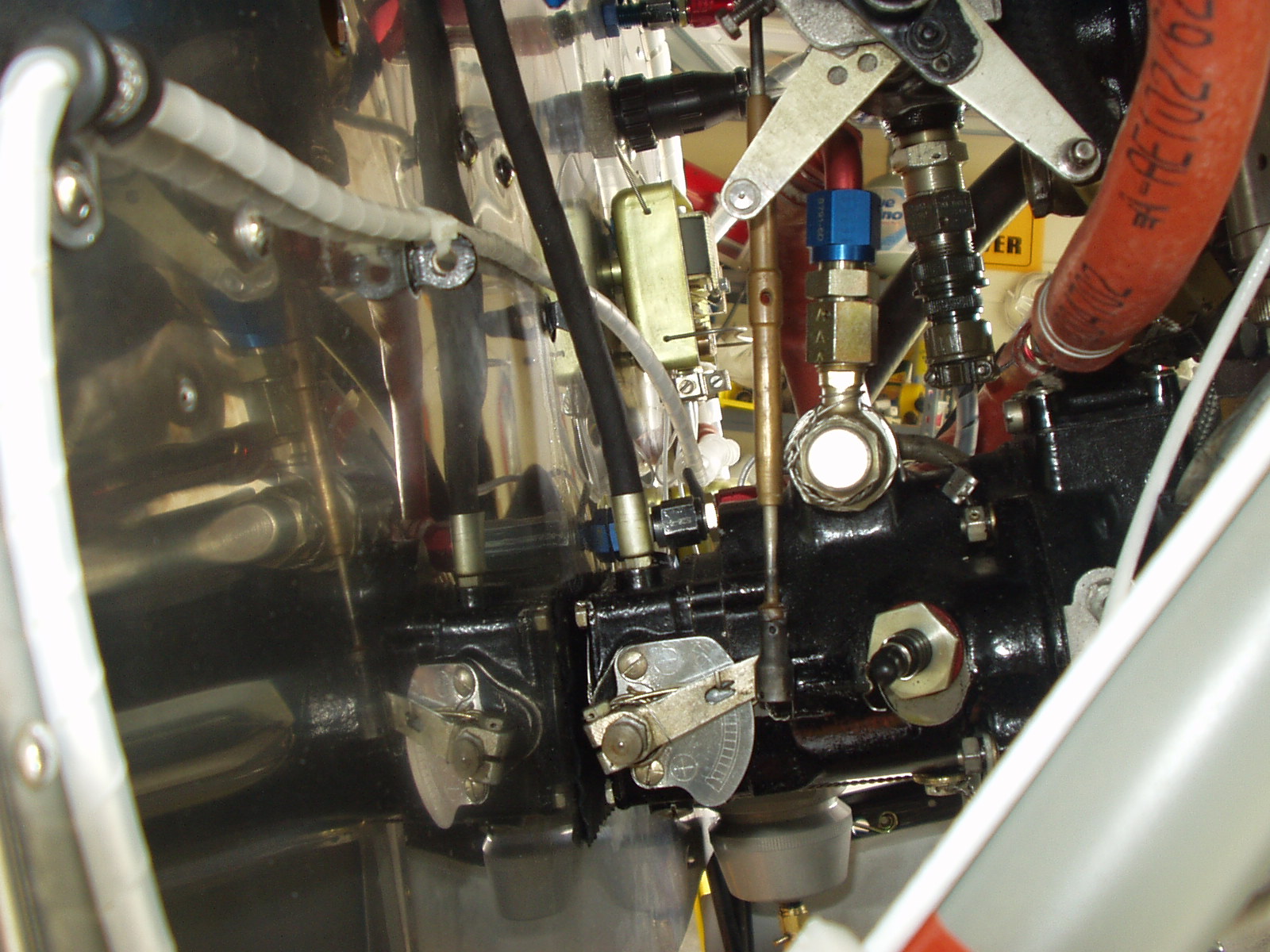
Conversation with other LOM operators have led me to believe that an in-flight mixture control is not really necessary. I turned the LOM push-rod into a turnbuckle so that my mixture is ground adjustable.
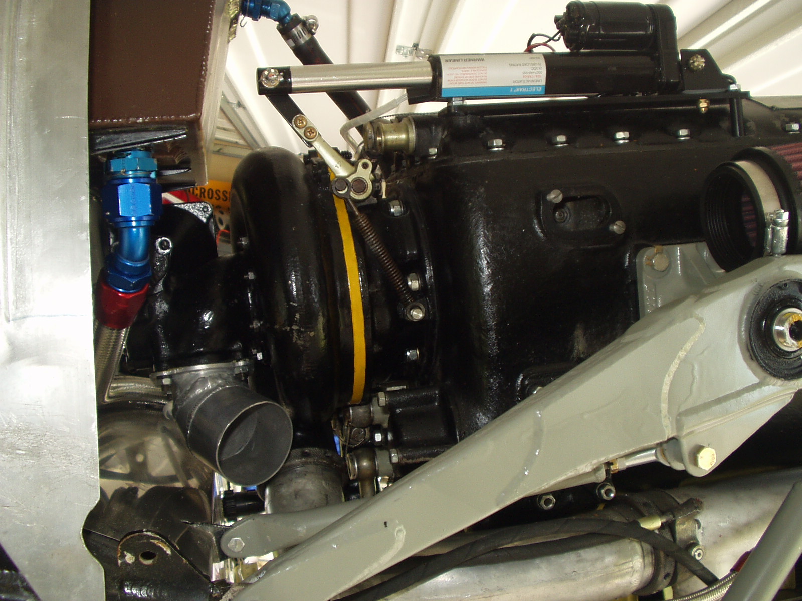
Here you can see my welded aluminum elbow for the air intake, the aluminum oil tank and my linear electric actuator that controls the super charger. It has a travel of 4" and a thrust of 70 pounds. It engages or disengages the super charger in about 2 seconds from a small switch mounted on the throttle quadrant.
The K&N air cleaner will mount to a bracket I am making that screws onto the opening near the top of the engine case.
I will document here the process I have endured in installing the LOM332 engine my way. I say "my way" because Joe Krybus will provide a complete kit to install the engine in a very straightforward way. As always, the quality of his products is fantastic. Those wishing to complete the engine change wile still young enough to fly the result would be well advised to use's Joe's kit 
I chose to modify Joe's installation because I felt it made the Jungmann look too long in the nose.

A Joe Krybus Bücker
The LOM is much lighter than the Tigre of course so Joe mounted the engine where it needed to go for CG considerations. He also wanted to maintain good access to the accessory section of the engine. I felt that with careful attention to the weight of the rear of the aircraft, battery placement etc., it would be possible to put the engine further back so that an original Spanish cowl could be used.I have still not weighed my a/c so the wisdom of this aproach is yet to be established.
This is purely a matter of preference. Joe's installation is almost exactly the same dimensions as a Czech Aero C-104 so his installations look very much like that aircraft. The German/Swiss Hirth installation is a little shorter, the Spanish Tigre the shortest of all. I happen to like the look of the Spanish cowl the best.
I chose to shorten the mount by 6 inches
It turns out that I was not alone in. Talmadge Scott from Florida had exactly the same idea and has already flown his aircraft. To fit the engine exactly in original Spanish sheet metal, Talmadge relocated one of the tubes in the forward fuselage to allow the engine to protrude about an inch through the firewall. He then covered this protrusion with a stainless steel cover.
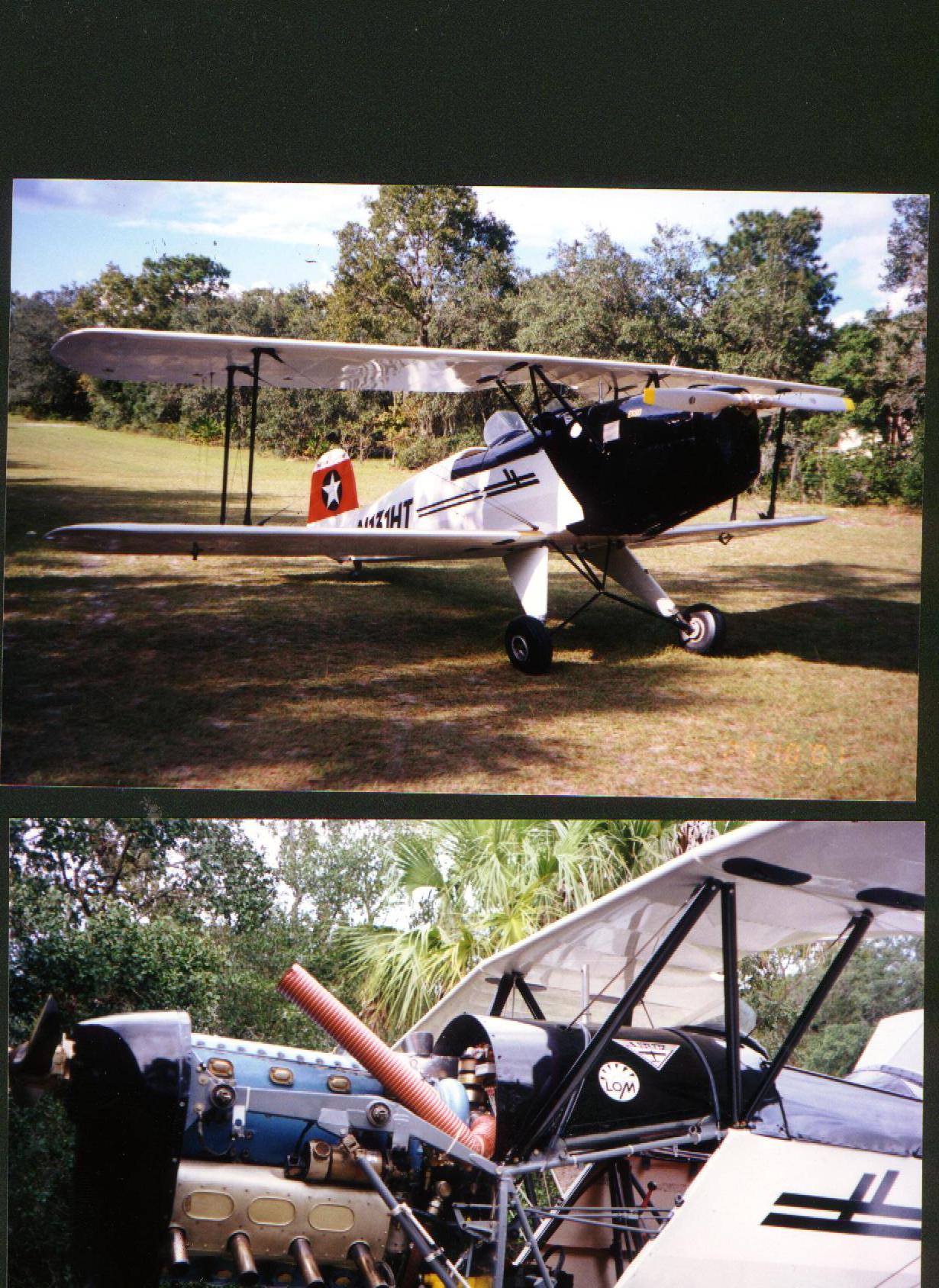
Talmadge Scott's LOM Jungmann
I took a slightly different approach. I found that the prop. hub from a Walter Minor engine fits the LOM perfectly but moves the prop aft about 1.5". This allows the prop. to be placed in the original place without the protrusion through the firewall. These prop hubs are now available for purchase from Moravia where it is listed as a "Bucker style" prop hub.

Walter Minor prop. hub
I had already bought my engine mount from Joe Krybus when I took the decision to remount the engine in this way. I made a wooden jig to help get the alignment just right and then cut and re-welded the mount to move the engine aft. You will find pictures of the process here and a sketch at the bottom of this page.

Original Krybus Mount Modified mount
Since I don't have an original cowl (my project came with no sheet metal) my next task is to build one. I have recruited a local race car body builder to help me get that nice curve in the top of the Spanish cowl.
Other factors to be considered in installing an LOM engine are:
Oil tank
The Spanish oil tank will no longer fit in it's original position on the firewall. I may use a Joe Krybus tank (which still fits the shorter mount) or I may make a saddle tank to fit in the space over the engine.
Supercharger control
The LOM supercharger control is a push-pull rod that required a force of about 50 lbs to operate. This is something of a challenge to arrange. Talmadge welded a tube through his fuel tank. Other have used a system of cranks and levers. I have taken a different approach. The Warner Electric company make a linear electric actuator which exerts a force of 70 lbs over a throw of 4 inches. It is about six inches long and very slim. I have mounted one of these units on top of the engine and control my supercharger from a toggle switch hidden behind the throttle quadrant. I used Warner model number S24-17A8-04. A more detailed description can be found here:
http://www.powerdrives.com/electrak/S24-17A8-04.htm
The decive costs a modest (by airplane standards) $175
Fuel System
Like many fuel injected engines, the LOM returns pressure bypass fuel to the tank. An extra port should be provided to allow this.
Finally, if I had to do it again, I would definitely not choose this approach. If you look at a Tigre tubular mount, you will see that it is very similar indeed to this mount, intended to attach an LOM to a GlasSstar. I would buy the mounting pads, rubber mounts and carriers and then weld-up a tubular mount similar to this. It would be much quicker and cheaper.
Steve

Notice the neat exhaust system available from Moravia.
How the Krybus mount was shortened
This sketch shows how I determined where to make the cuts in the engine mount as received from Joe:

Clamp the mount to your workbench with some poster board under it and draw round it (the mount, not the work bench.) Then with a fresh piece of poster board, under the mount draw round just the section from the mounting hole 'A' to the rear engine mounting pad and cut out this second piece with scissors.
Take the outline drawing of the whole mount and using a straight edge and a square, mark the location of the new mounting bolt position 'B' exactly six inches to the right of the original hole and perpendicular to the firewall.
With a push-pin, pin your cut-out section (shown in red above) through its mounting hole, to the new hole position 'B'.
Rotate the cut-out section until it intersects the original mount in a pleasing way and then mark the top and bottom intersects on both the outline drawing and the cut-out section. (Shown as green dots in the sketch).
Now when you join those dots, you have the exact lines on which to cut the engine mount. (You will make two cuts of course)
Note that the sketch is not to scale and I have exaggerated the angles for clarity.
An alternative method, (which I did not use because I did not want to distort the engine mounting pad) is to cut the mount at the rear mounting pad, grind the exterior of the pad smooth, cut a new radius in the cut-off section and re-attach it to the pad at the correct angle. I believe Talmadge Scott used this method.
Steve
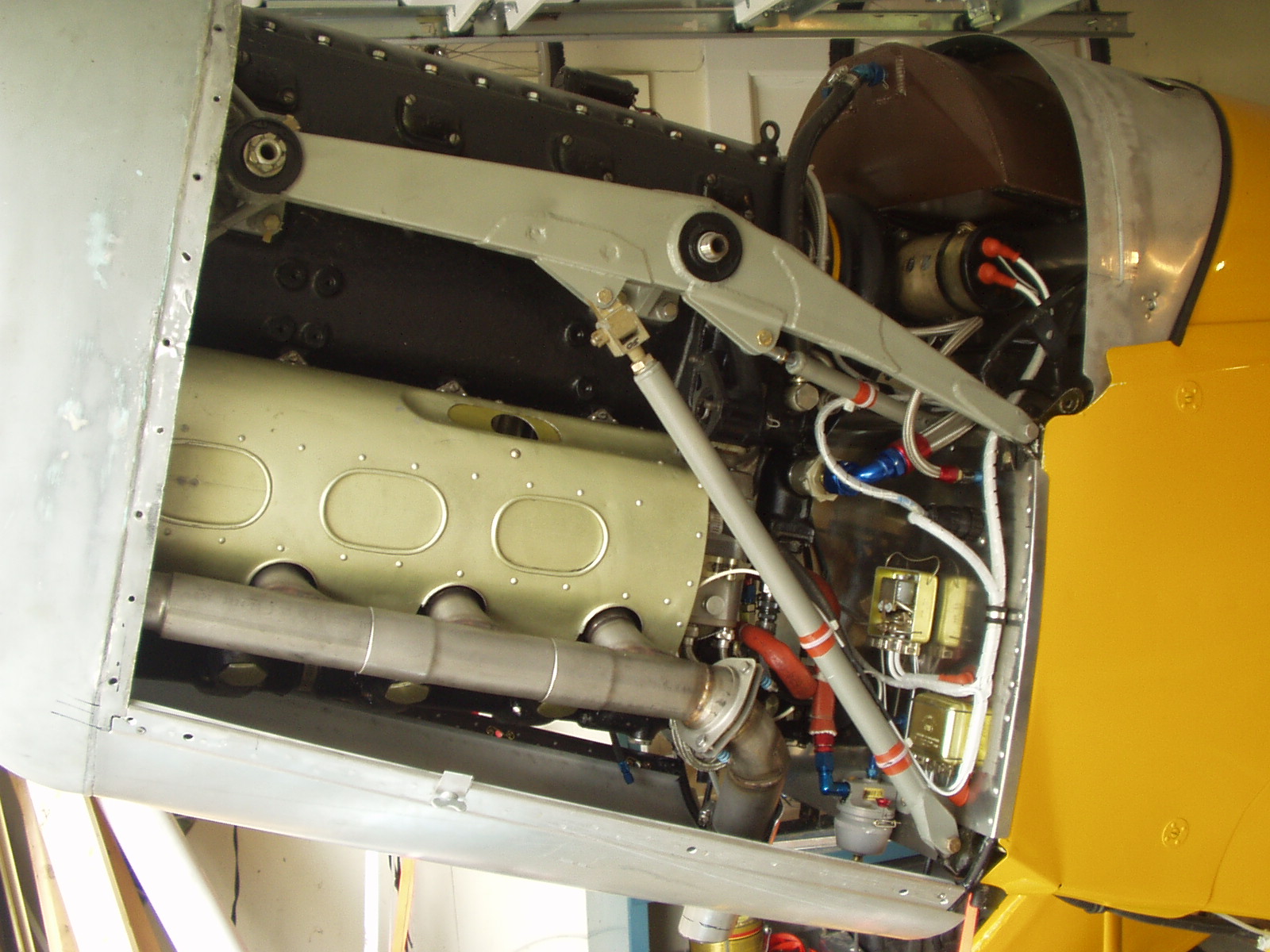
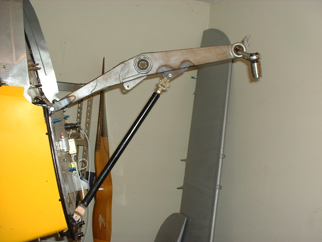
The installation of my LOM engine is at last complete. - Way too early to tell where the CG will come out but here are a couple of pictures of the mount. Notice the cross braces - made from the originals but with a rod-end bearing. I used the original diagonal brace mounts with a spacer inserted between the two ears.

